

Subsonic Wind Tunnel
By Tyler Wempe
August 13th, 2026
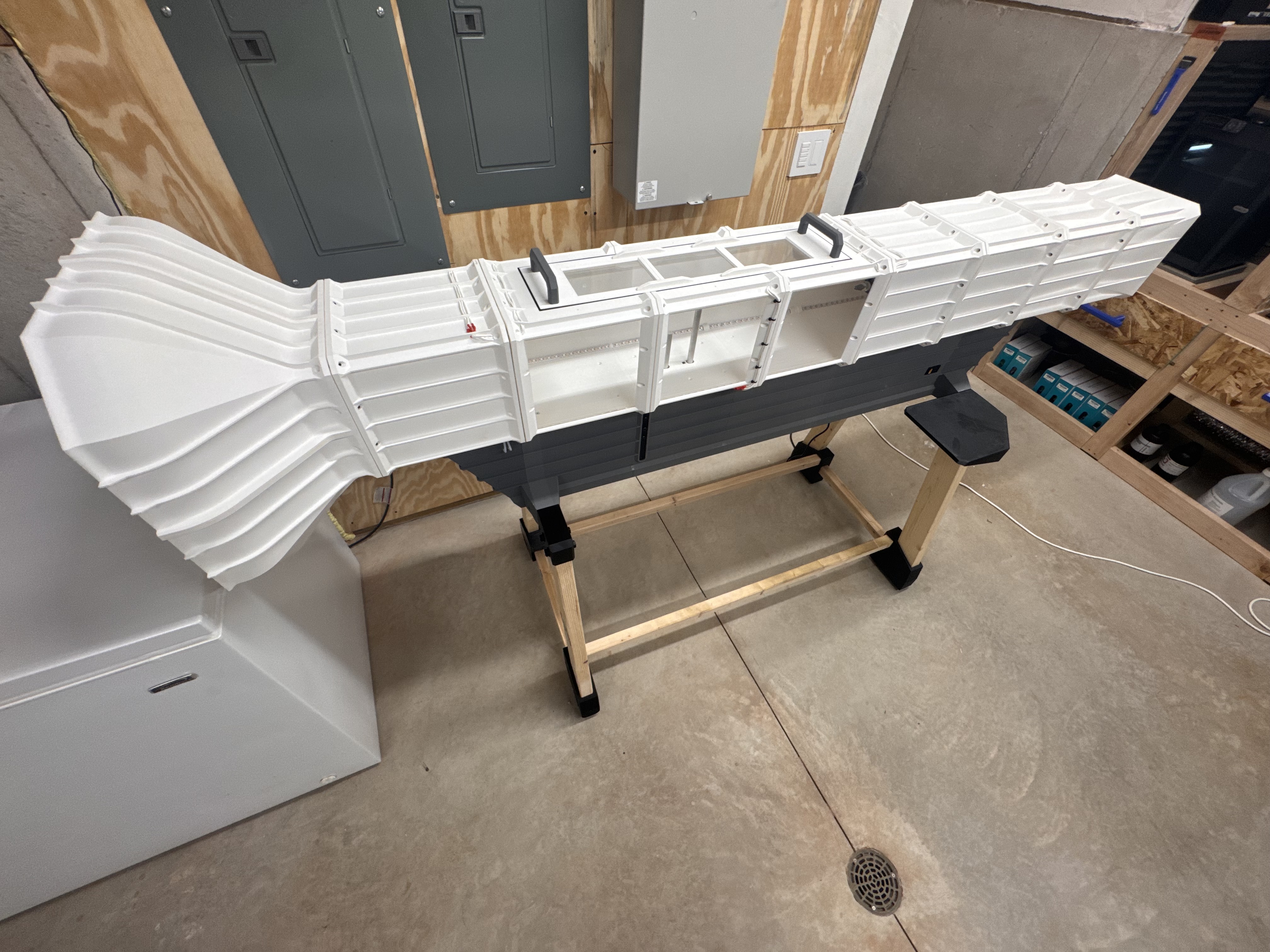
Wind Tunnel Image - Tyler Wempe
Advertisement
Introduction
At the end of my junior year of high school, I was thinking of what I was going to do that summer, and I decided to make a wind tunnel. Why you ask? I wanted a project that further challenged my CAD skills and something that kicked off my understanding of electrical engineering. My goal was to finish it that November, just before college applications were due, but that didn't come to fruition. In November, I was still working on the undercarriage of the tunnel where the electronics, load cells, sting mechanism, etc were housed. To this day, I still don't consider it complete, but maybe one day. Below is my journey through this project:
Design Goals
For this project, there was a few key features I wanted to make the project challenging and useful at the end. Here were my main goals with explanations below:
- Modular Tunnel Sections
- Large Internal Profile
- Load Cells
- Prop Test Module
Modular Tunnel Sections
Firstly, I wanted the tunnel sections to connect and disconnect easily in case of damage and to allow large test subjects to fit into the tunnel. It also allows for upgrades (like adding a second fan). The sections are connected together with 12 bolts along with a TPU seal to prevent the internal airflow from being disrupted.
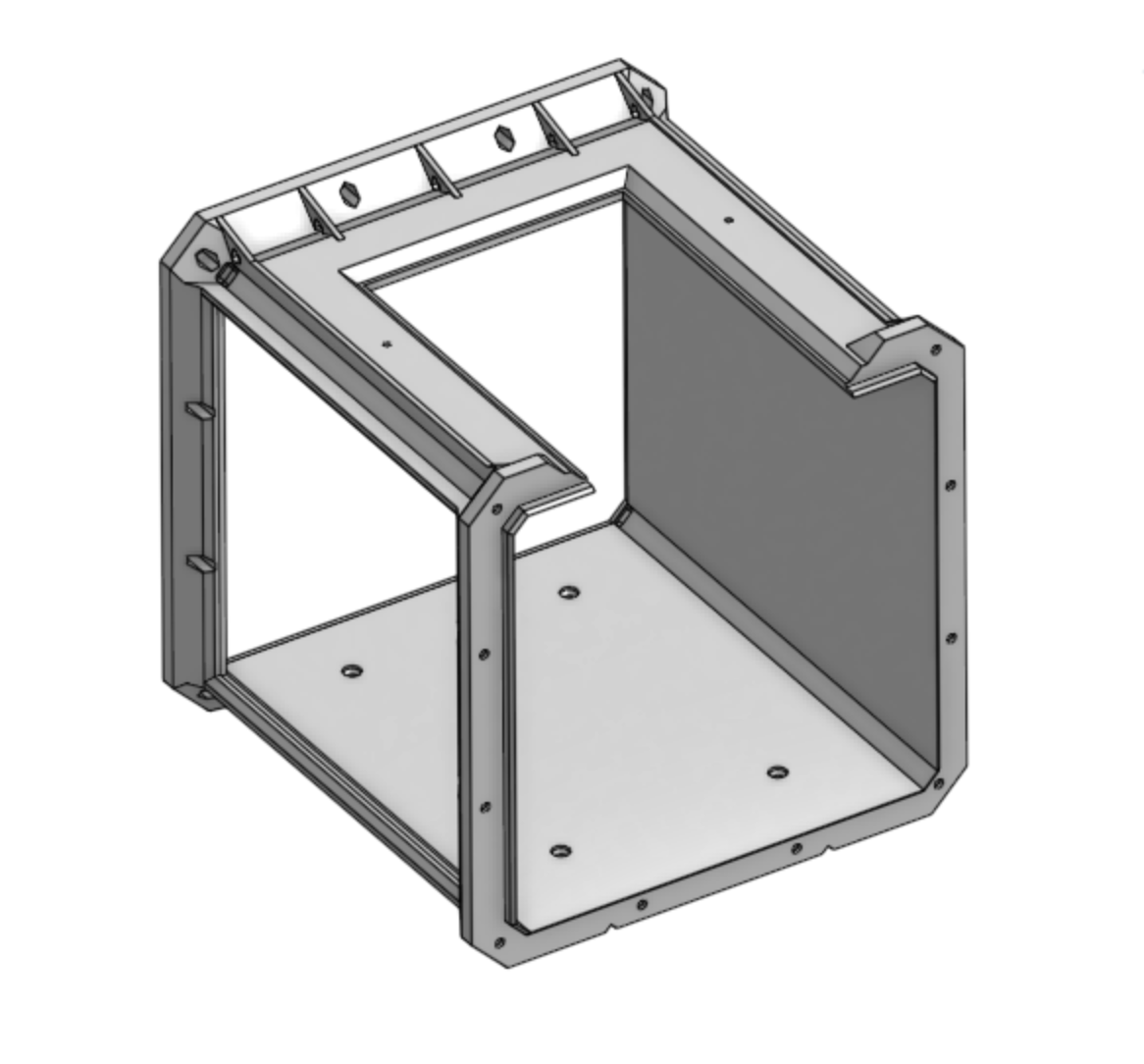
This is the first full tunnel section, just after the pitot tube.
Large Internal Profile
I've always believed bigger is better, so I wanted to make the tunnel that way. I knew a section would either have to fit entirely on the 256mm x 256mm build plate of my Bambu Lab P1S, or it could be broken up in 4 corners so make tunnel way bigger. I chose the first option because it would be stronger, and that would be a lot of filament. The design I fell upon has a 218mm x 218mm internal profile, which was unfortunately limited by the bolts/nuts next to the window panes.
Advertisement
Load Cells
I wanted to get actual data when this was done so I decided to put lift and drag load cells into the sting mechanism. These are 5kg load cells reading pressure forward and backward (drag) and up and down (lift). They are connected to the sting and adjust to give more room for subjects in the tunnel. They are housed in the tunnel underbelly. This design, along with the sting angle mechanism, was tricky because it couldn't simply be mounted directly to the underbelly or the load cells wouldn't give accurate readings. I also added a thrust load cell (10kg) to the propeller testing module in the back of the test section to get propeller data like efficiency.
Prop Test Module
To make the wind tunnel even more useful, I decided to add a propeller testing section with a 1400kv brushless motor. On the backside of the motor, there is a wheel with 2 magnets mounted oppositely for symmetry while the motor spins at high RPM. The RPM is then calculated with a hall sensor near the wheel with magnets. Along with the thrust load cell (10kg), I can measure propeller characteristics such as efficiency.
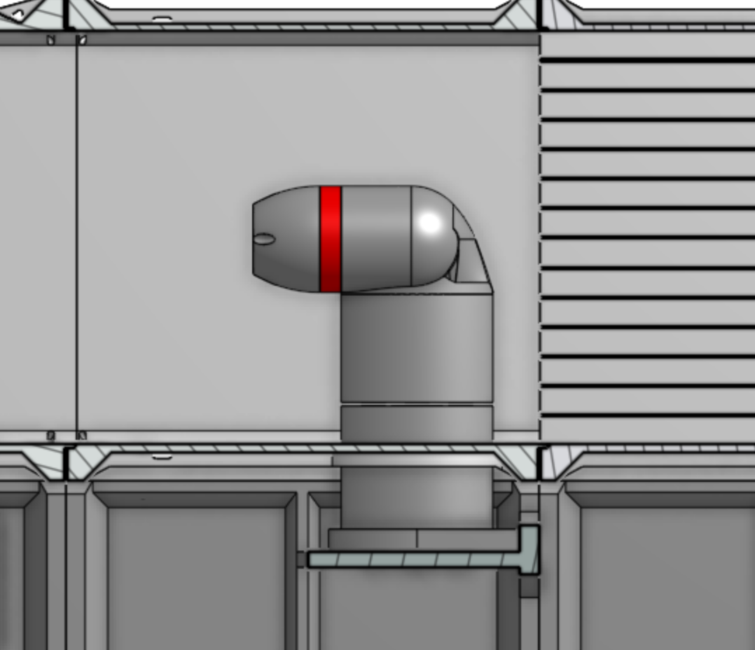
This is the propeller section, it has a aerodynamic arm steming from the underbelly that hides the cables and load cells.
Advertisement
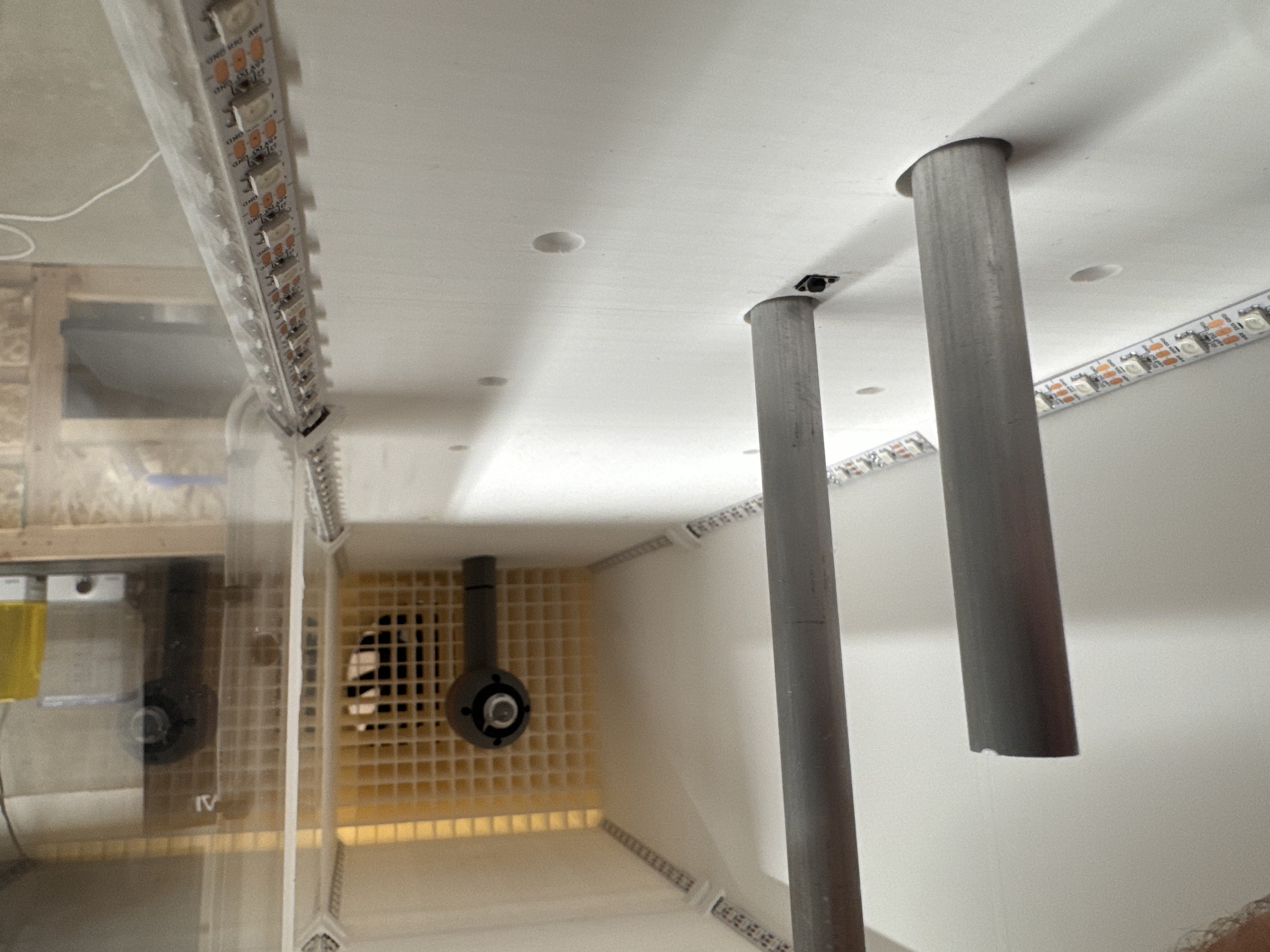
The inside of the tunnel showing the two sting posts, the prop test module, and the rear flow straightener
Challenges
With such a big projects comes a few problems. Below are the biggest challenges I faced:
- LED Light Wiring
- Print Warping
- Sting System
- Power Distribution
LED Light Wiring
Because each tunnel section needed to be modular, I didn't want the LED strips connected in a chain because I would need a small gauge wire for the early strips in the chain because the LED lights draw a lot of current. I decided to wire each section individually and connect them to the 5V buck converterindependently. Then I routed 3 wires through each corner of every section and started the LED strip.
Print Warping
One issue I didn't forsee at all was the warping of the tunnel sections. The printed each section with an internal brim so adhesion wasn't the issue, but it still was warping. The warping was so strong that the force overpowered the magnetic force of the bed plate on my P1S and was lifting up the corners. I think the only way to resolve the issue is to get a good heated enclosure. The prints had so much time to cool down because of the sometimes near 30 hour print time so the warping was inevitable with my printer.
Advertisement
Sting System
I would consider the sting system to be my biggest challenge because of all the requirements:
- Change the Angle of Attack to ±45deg
- Allow the whole sting to move up or down
- Apply ALL lift force to the lift load cell
- Apply ALL thrust force to the thrust load cell
- Keep the two sting posts the same distance apart
With all these requirements, I worked through many design iterations and did mulitple CAD simulations to ensure this design would work. Below is the image of the design. Not in the picture are, amoung other things, are two linear rails connected to each load cell so they don't intefere with each other. These rails run perpendicular to each other (like how the load cells are mounted).
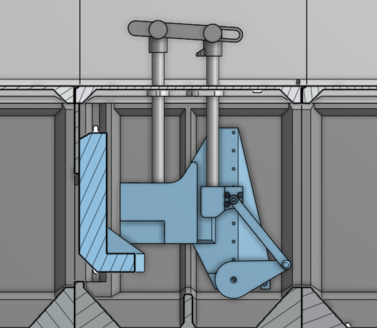
The blue section can slide up or down to allow the more room for a test subject. The angle of attack is controlled by the crank and slider mechanism which has a servo (not shown).
Power Distribution
A challenge I am still working on is power distribution. Particularily on the 5V end with the Arduino R4 Minima brain. Because the LED lights take so much power, it seems the Ardunio is being starved (but still stays on) because the sensors it is powering turn off. Even though my the LED draw is far less than the 20A maximum of my buck converter, it somehow isn't getting power. Because I am not an electrical engineer (or even been to college yet), this is an ongoing struggle and I continue to fiddle with capacitors and wiring changes.
Advertisement
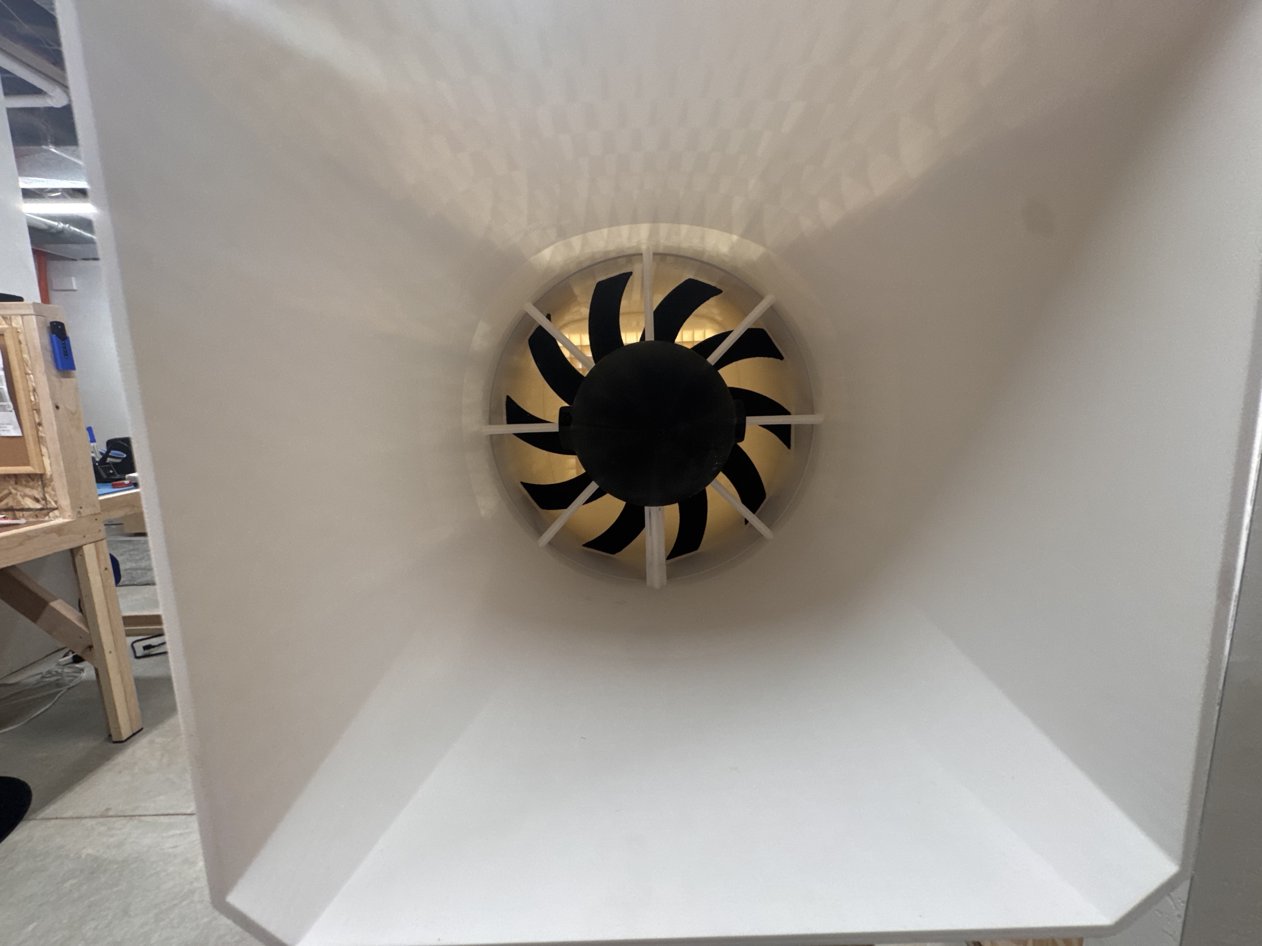
This is a picture of the rear of the tunnel. You can see the main tunnel fan, which is a 9" radiator fan.
Specifications
| Item | Specification |
|---|---|
| Main Tunnel Fan | 9" Radiator Fan, 1730CFM, 12V 80A |
| Flow Straighteners | Individual ~14.8mm square profile; 140mm long |
| Test Section Dimensions | 900mm x 218mm x 218mm (36in x 8.5in x 8.5in) |
| Full Dimensions (with Stand) | 2.2m (7.4ft) x 0.7m (2.3ft) x 1.3m (4.4ft) |
| AOA Servo | 20g Digital Servo |
| Main Stability Method | 22mm diameter stainless steel pipe running parallel with the tunnel |
| Window Panes | 1/4in thick 8x8in plexiglass sheet (not perfectly square) |
| Max Tunnel Speed | 20MPH |